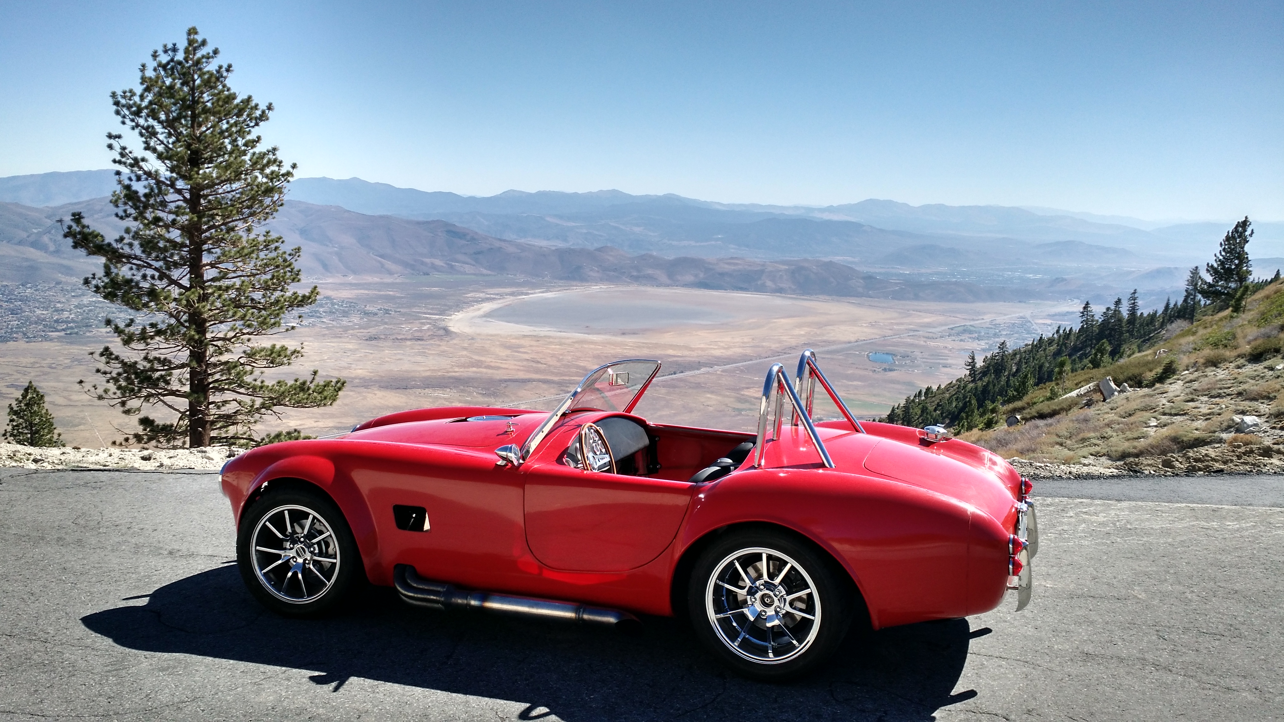
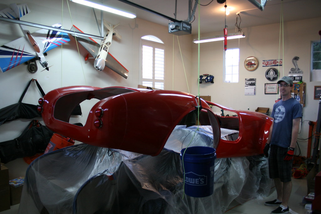
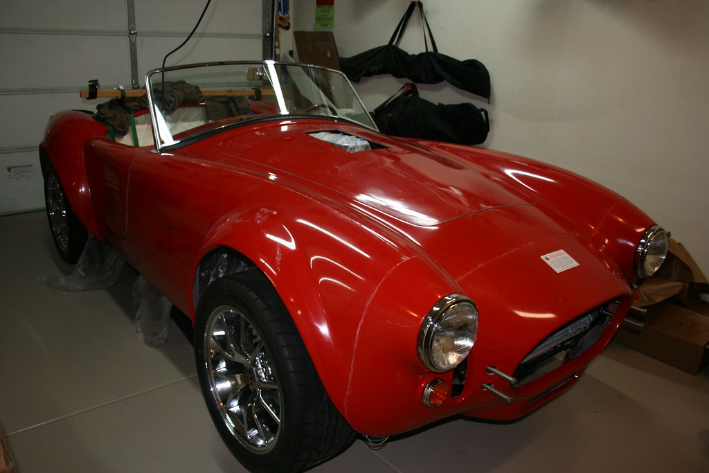
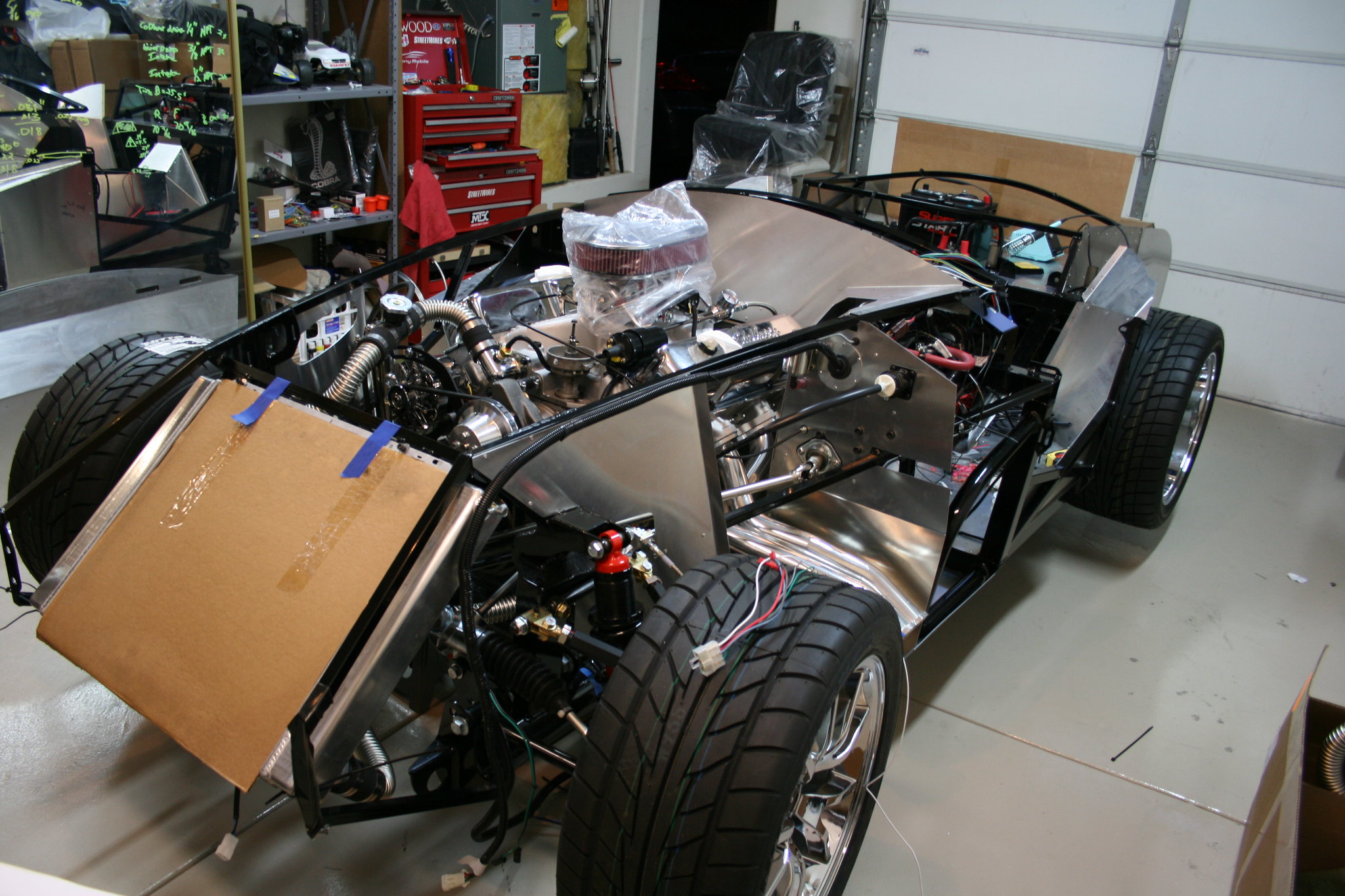
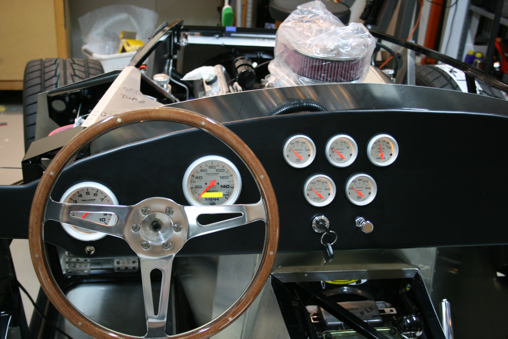
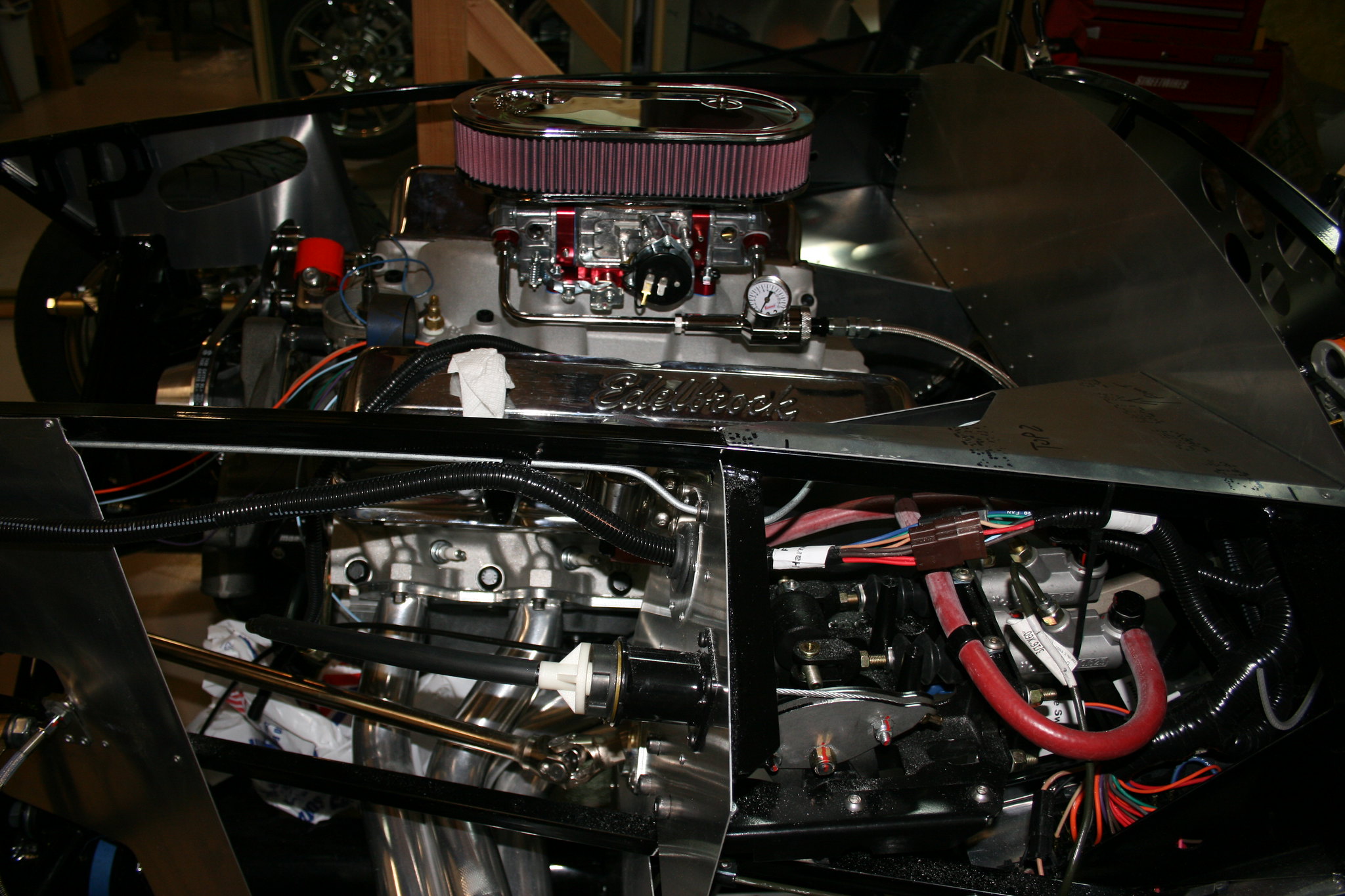
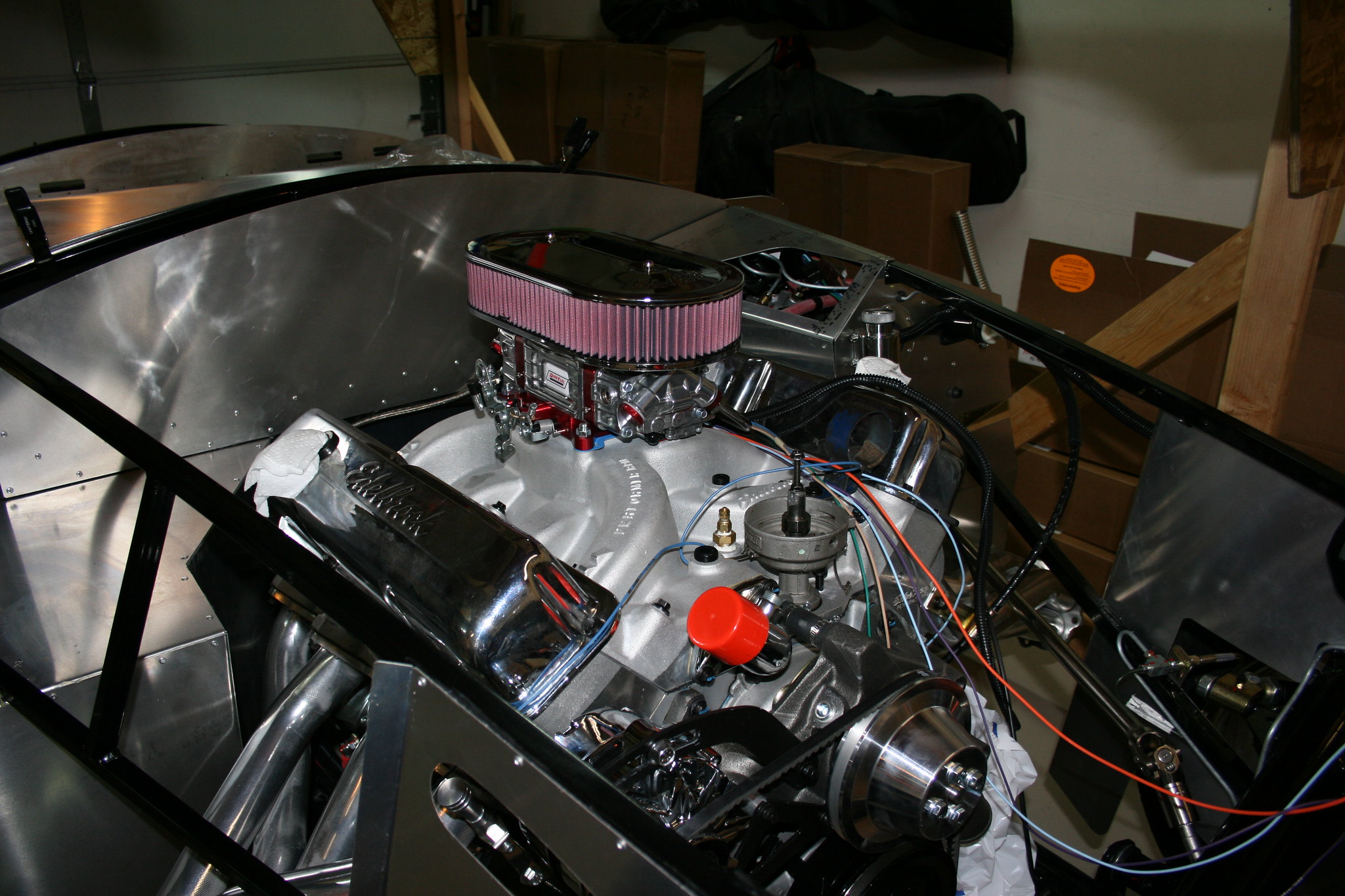
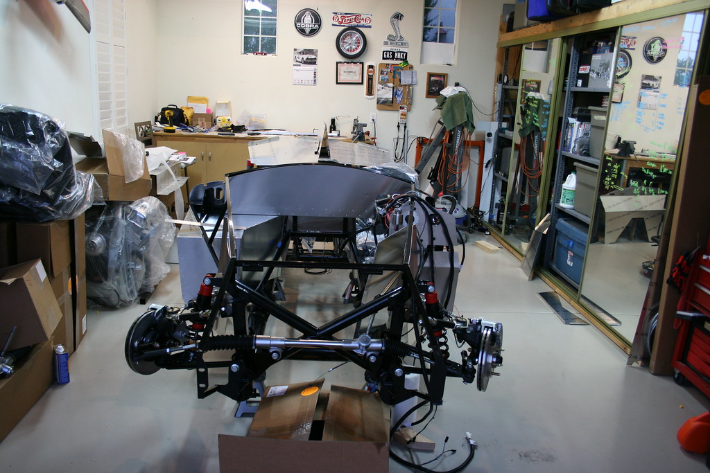
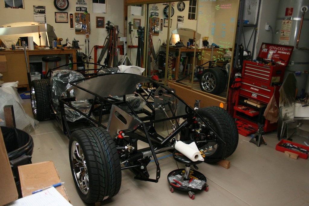
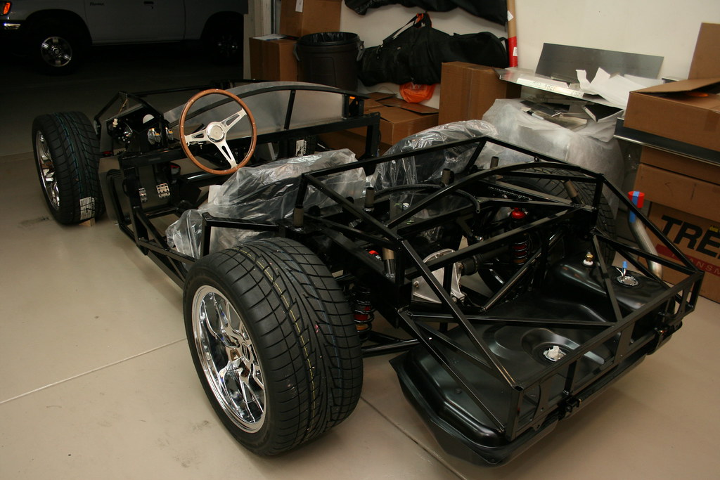
After many shake down runs, and tweaking things it's ready for paint. I talked to quite a few places in Reno. Most weren't interested in the work. Most that were quoted $10k. I talked to one place that did boat work and they were around $8k. So after a lot of looking, I decided to get a hold of Ken Pike in Yuba City. He's basically thee northern west painter for factory five cars.
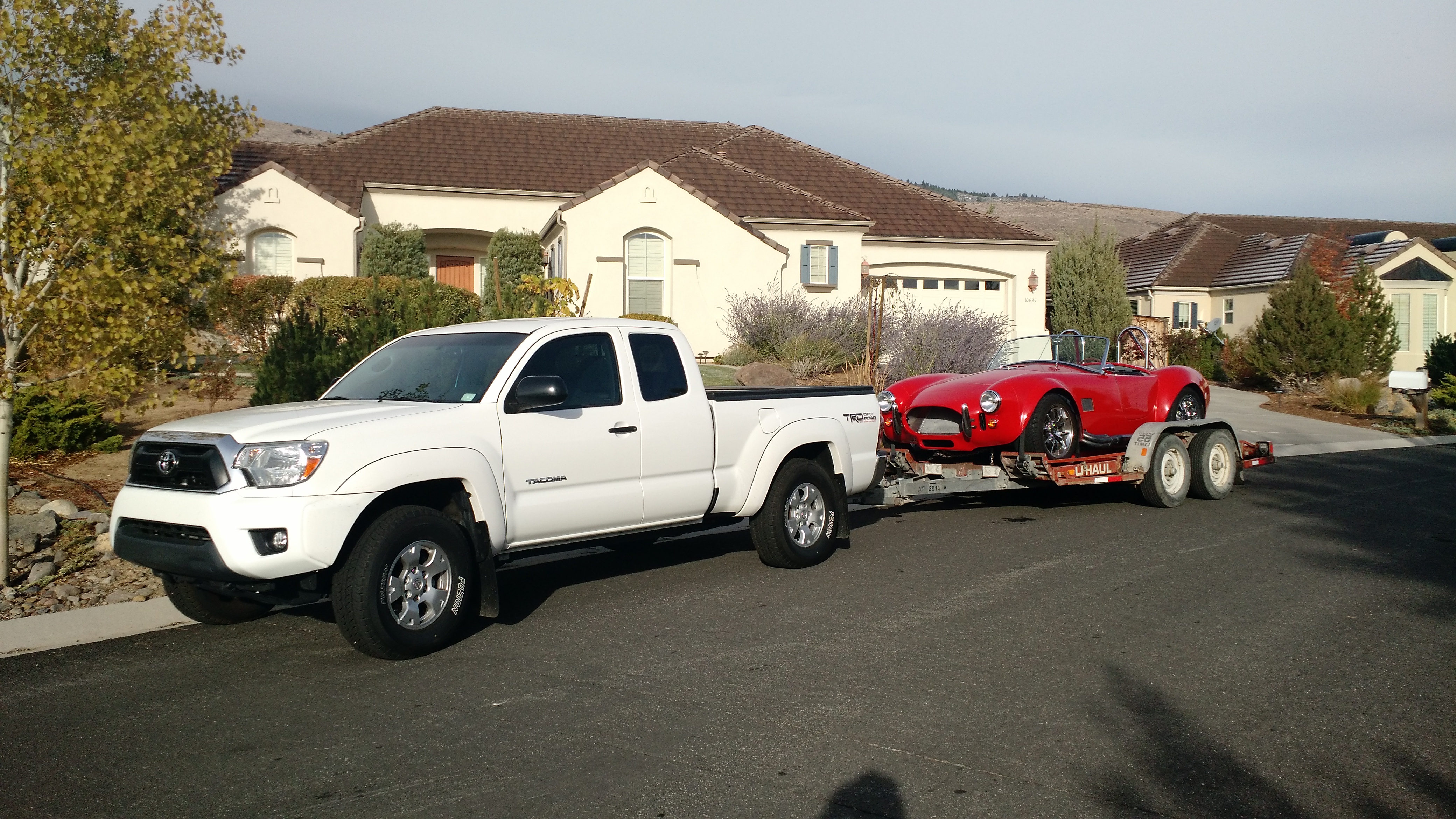
So I bit the bullet and my father in-law and I loaded the roadster up and on a U-haul trailer and drove over the hill to Yuba city. The Tacoma did surprisingly well getting it up over the hill.
When we got to Yuba City Ken helped get it unloaded and I told him what I was looking to have done. I had made my own fiberglass hood scoop using the plastic one that came with the kit to make a mold. I explained that I wanted that scoop bonded and blended in to the hood and Ken said no problem. He gave me some good ideas on paint colors and showed me some samples. With the car and half the money down we were good to go.
Taking lots of short rides around town. Check things out and getting used to things. I've run in to a few small issues but nothing major so far.
The fan relay quit on me for no apparent reason. Luckily I've been looking at all the gauges at every stop light and sign so I noticed before it got to hot. It cools great when moving, but needs the fan at idle. Replaced the relay and it's been good ever since. A spare is in the tool bag.
Found I've got oil weeping from the between the intake and the block at the rear. I'll have to tear into it to fix it.
Ended up increasing the accelerator pump nozzle a couple sizes to help with a bit of a bog accelerating off idle and I've been playing with timing and mixture adjustments to get it running just right. I've got occasional dieseling, but I'm hoping timing and carb adjustments can make that disappear.
With the go-kart stage compete and everything working great it was time to get the body re attached to the chassis. I opted not to have any of the holes cut in the body by the manufacturer so I got out the body saw and went to town cutting holes for the headlights, turn signals, and taillights. With those holes cut, I reinstalled the body.
Once the body was reinstalled I worked on cutting holes for the windshield to install through as well as the roll bars. The hood, deck lid, and doors are all cut a little oversize from the manufacturer so with the body installed I started attaching and fitting those pieces. Sanding fiberglass is messy and itchy, but I got everything just fitting.
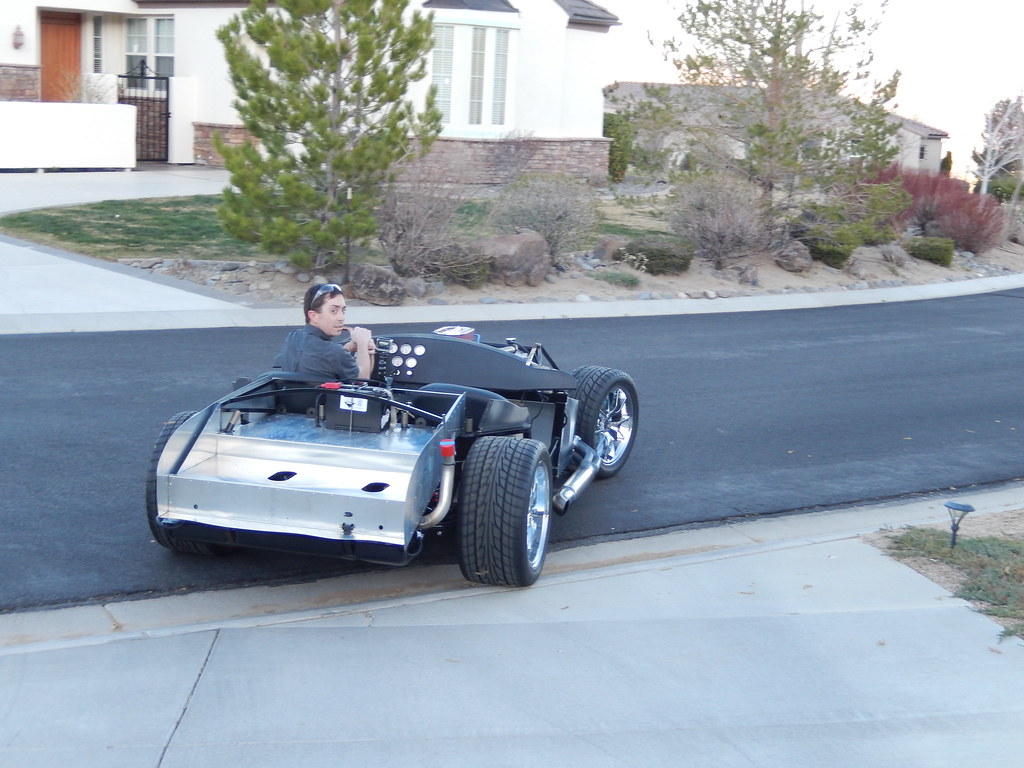
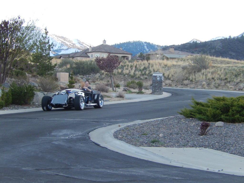
First go kart drive! Down to the end of the cul-de-sac and back. No real problems. The brakes are soft, but that's because everything is new. I just need to bed them in. This thing is gonna be awesome.
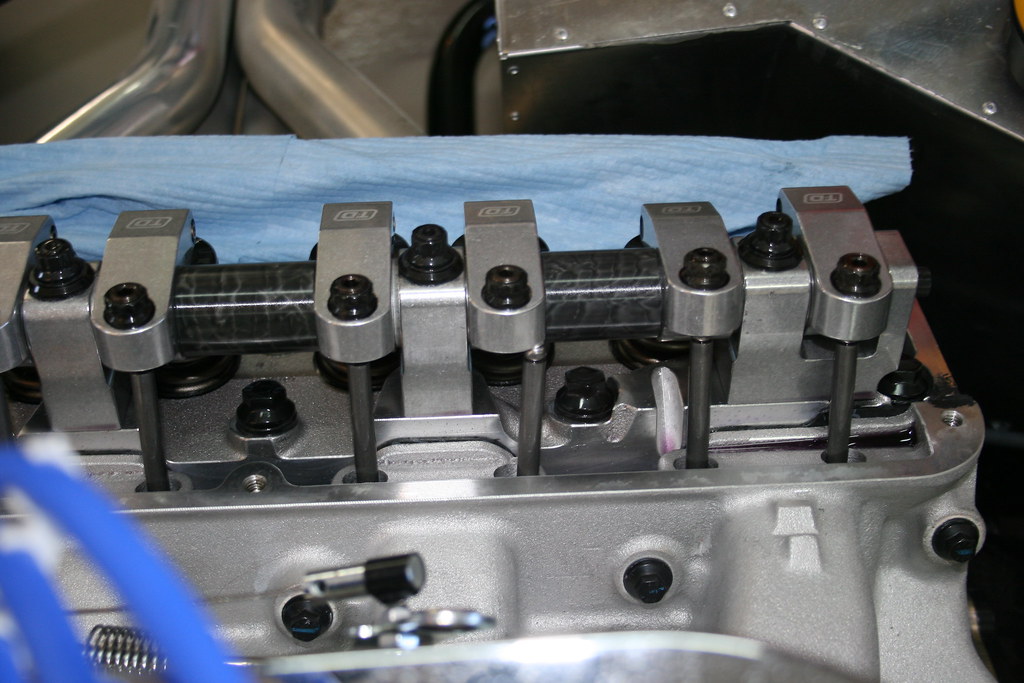
With engine breakin done and a heat cycle on the engine it was time to check torque on engine fasteners. When I pulled on the valve covers I found that one of the push rods had come out of it's cup on the rocker. :( Totally did not expect to find that since it ran so great during the breakin.
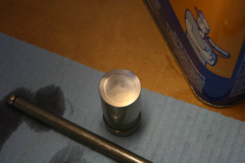
In an effort to determine the cause I pulled the lifter out (an extendable magnet through the distributor hole, an inspection camera, and patients). Could find anything wrong at first glance with the lifter. I ultimately took the lifter apart and did find a sliver of metal inside. Not sure if that was the cause or not, but it caused me to pull the lifter next to it as well. That one showed a wear ring where the lifter contacts the camshaft. Can't actually feel anything, but you can see it.
I ended up sending pictures to Comp Cams tech support and at there suggestion I decided to pull the cam and lifters. I just didn't want to risk it happening again, or having a worn out cam and lifters in a few hundred miles.
So I replace that camshaft and lifters with a hydraulic roller. Another Comp Cams, but this time 282HR grind. No break in required on the new camshaft.
With the new camshaft installed and everything buttoned back up, we fired it up again and everything is good to go.
With the dash assembly completed and cooling system tightened up it was time to fire up the engine for the first time.
I made a bunch of trips with the 1 gallon gas can to the gas station, 5-6 gallons in put the fuel gauge at about a 1/4 tank. Turned the key to ON and the fuel pump fired up and I had just over 7lbs of pressure at the carburetor. Fuel in the carburetor fuel bowls was just slightly over half full.
Next step was priming the oil pump. I had converted the old distributor to an oil pump primer. I ran the drill on the modified distributor in reverse and had 50lbs oil pressure on the gauge. With good oil pressure, we ran the oil pump while we made 2 full revolutions on the crankshaft trying to make sure that oil was forced everywhere.
With the engine primed we installed the real distributor. Aligned the 10 degrees BTDC timing mark on the harmonic balancer with the pointer. Then slid the distributor in and aligned the number 1 spark plug terminal with the rotor tip (we'd find out later that this really put timing just about right at TDC).
With distributor in and positioned correctly, a quick once over of everything to see if something was missed and then we pushed it into the driveway. I had wet towels, fire extinguisher, and an assortment of tools at the ready.
Turned the key to ON then to START. Engine cranks over for a few seconds sputters and quits (I was giving it a bit of gas thinking that it wouldn't just idle, I should have just left my foot off the pedal). Crank #2 for a few seconds and nearly started (i'm still trying to hard withe gas pedal). 3rd crank and it fires right up. I give it gas and get it up to between 2000 and 2500 rpm for the cam breakin.
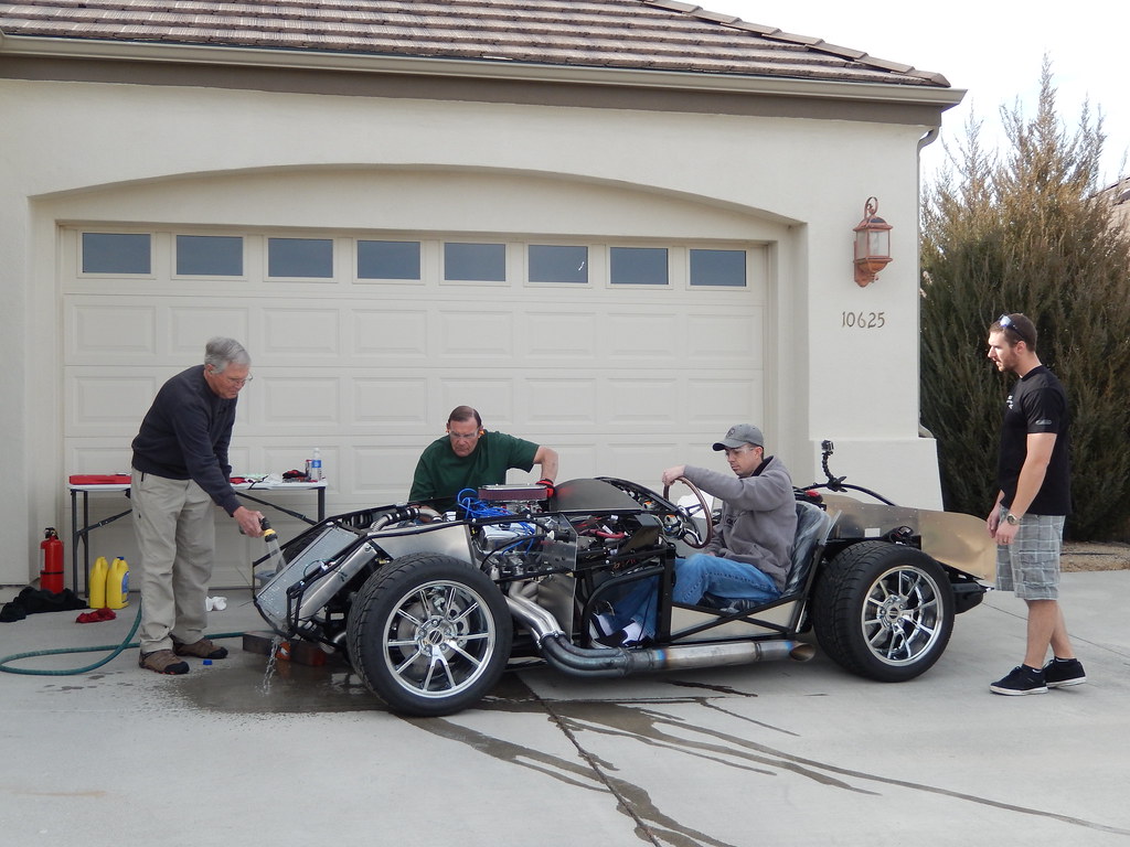
The car is so loud at that RPM you can barely hear yourself think let alone try to communicate with anyone else. After 7 or so minutes coolant starts coming out of the overflow causing me to shut it down. Checked the cooling system and figured there must have just been some air in the system. Found out the timing was only around 7 degrees BTDC. I wanted it closer to 20-25 degrees at that RPM (later I learned up around 30 is probably even better). Adjust the distributor a bit to advance timing and fire it up again. Watching temp gauge and oil pressure gauge. Once the temp got up to 210 degrees I shut it off not feeling comfortable about how hot it was. Let it cool for a bit thinking about how to keep it cool. The neighbor brought over a fan. Fire it up with the fan blowing, and it still got a little hotter than I was comfortable with.
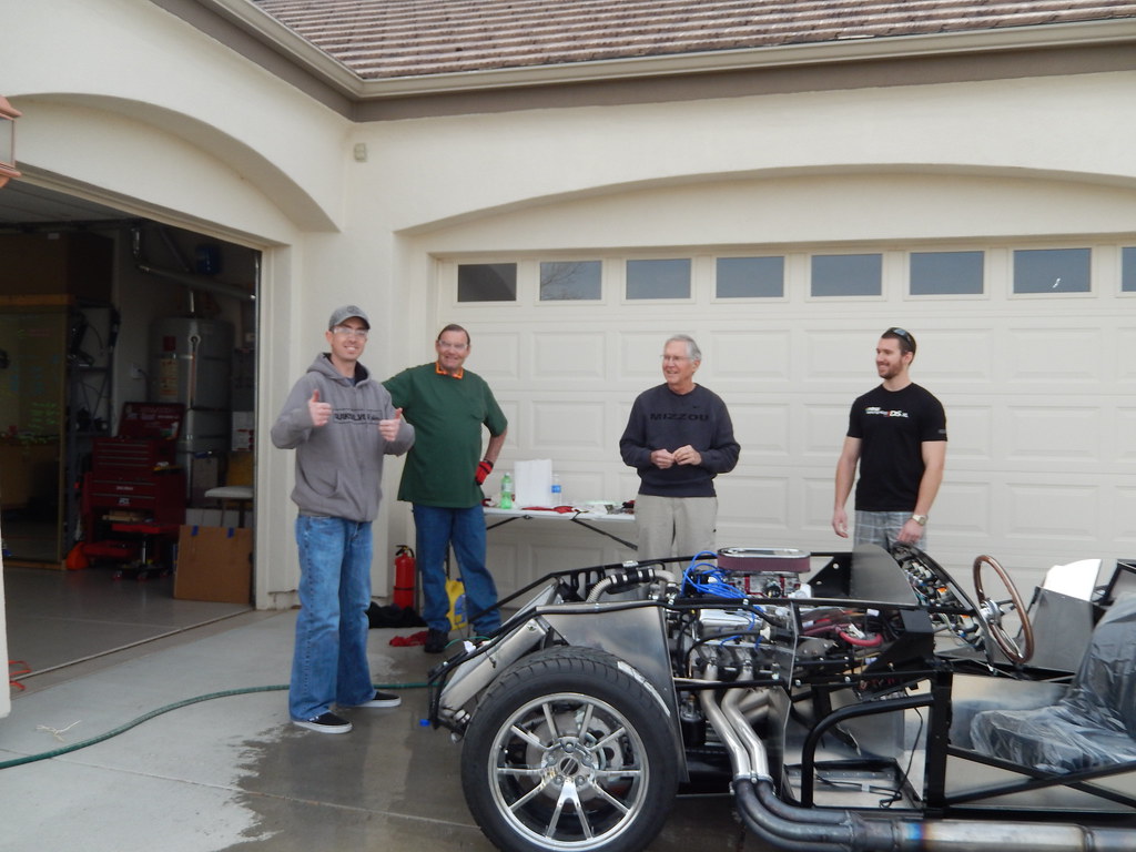
Finally the bright idea came to me to just run a garden hose over the radiator to help keep the temp down. That got it for the remained of the cam breakin! It's Alive!
So the next weekend I was able to spend a lot of time in the garage. I started out working on the dash. I decided I wanted it to be as simple as I could make it. I didn't want a cluttered dash with a bunch of switches, buttons, and lights. I basically have all the gauges (RPM, Speedometer, oil pressure, water temp, fuel level, oil temp, voltage) and three switches (turn signal, ignition, headlights), and that's it on the dash. Switches for high beams, horn, and seat heaters are all just under the dash. I'm leaving off indicator lights for high beams and turn signals for now. I'm thinking about trying to incorporate them into the gauge illumination.
I also decided I didn't like the way they suggest attaching the dash to the frame. Screws through the dash leave screw heads visible on the front of the dash. Since I was trying to keep the dash clean I decided to make some brackets and rivet them to the back of the dash so I could mount it to the frame from behind.
Once I had the layout of all the pieces I cut the holes in the aluminum dash for the switches, attached my brackets and then glued the vinyl cover to the aluminum panel. I used every heavy object I could find in the garage to help ensure the vinyl pad would stay stuck to the aluminum panel.
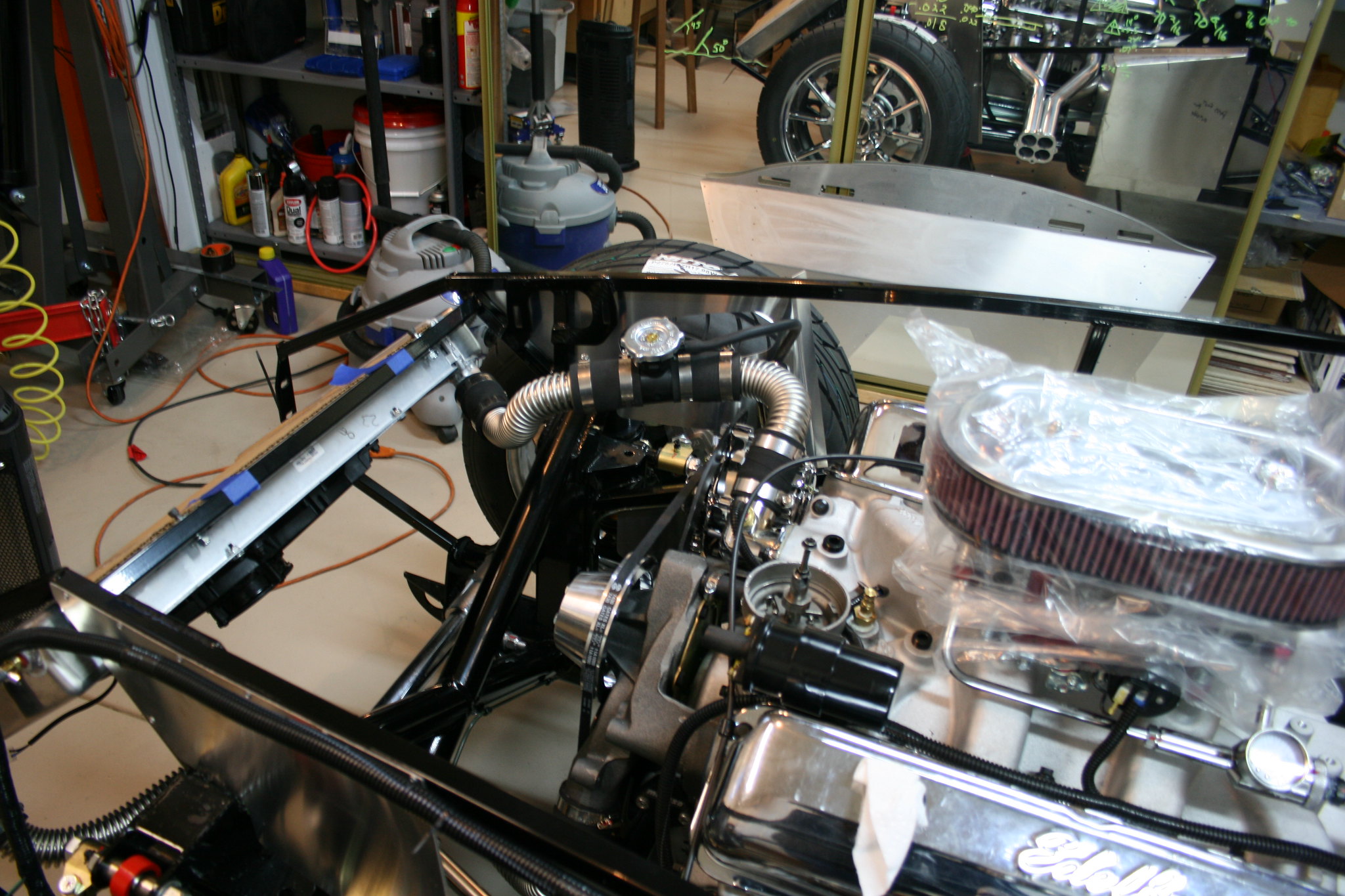
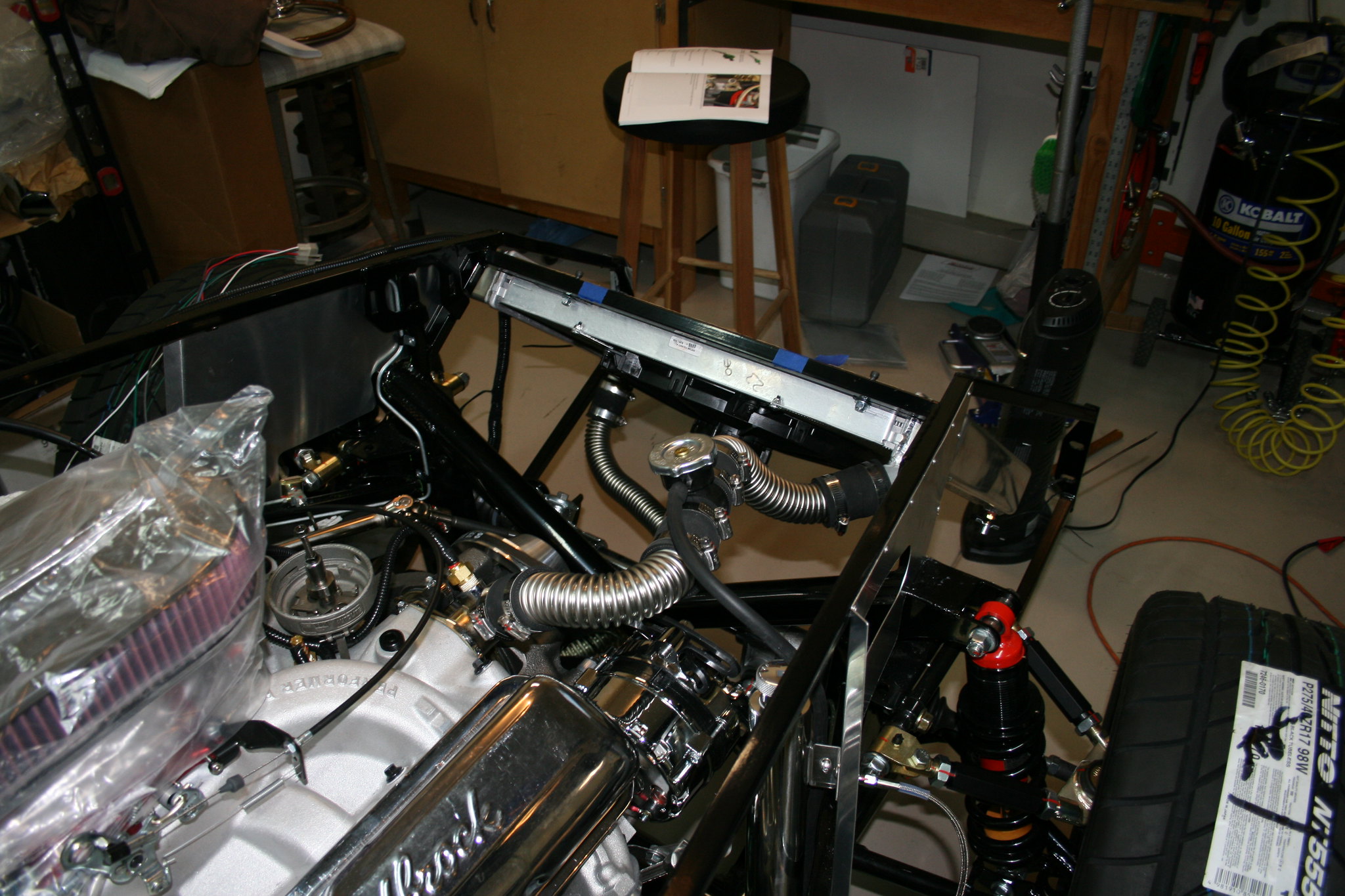
While the dash dried I got to work on the cooling system assembly. I mounted the radiator to the frame and used the supplied hose and fittings to get everything connected. Nothing to difficult here. I still need to find a better attachment for the lower hose to the frame, but the zip tie will hold it for now.
With the wiring in rear basically ready to go. I moved on to the engine bay again.
I installed the fuel line connections on the carburetor and mounted the carb to the engine. Then I got the accelerator cable attached and adjusted, and installed the aircleaner assembly. I also threw on the exhaust headers just to see how'd they fit. Everything went pretty well. The accelerator cable took a bit of time to get adjusted, and there will probably be a bit more adjustment once it's running.
Now it's time to really start connecting things
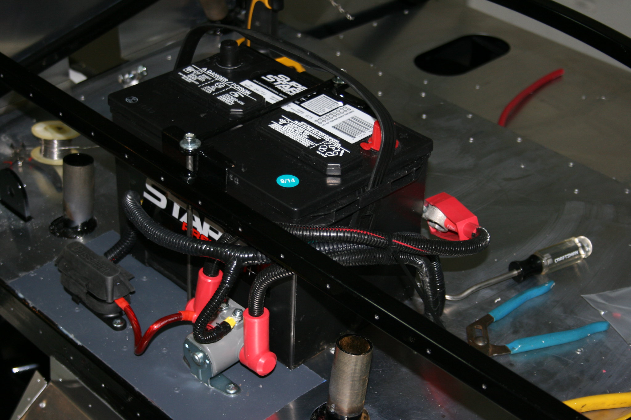
I decided that I'd change the wiring a bit. The starter solenoid is generally located in the engine bay and that would have been fine, but I didn't like the idea of running a large gauge un-fused power cable from the battery in the trunk to the starter solenoid in the engine compartment.
So, I decided to move the solenoid to the trunk with the battery. This allowed me to keep the un-fused portion short and also incorporate a Mega fuse to feed power to the fuse block under the dash.
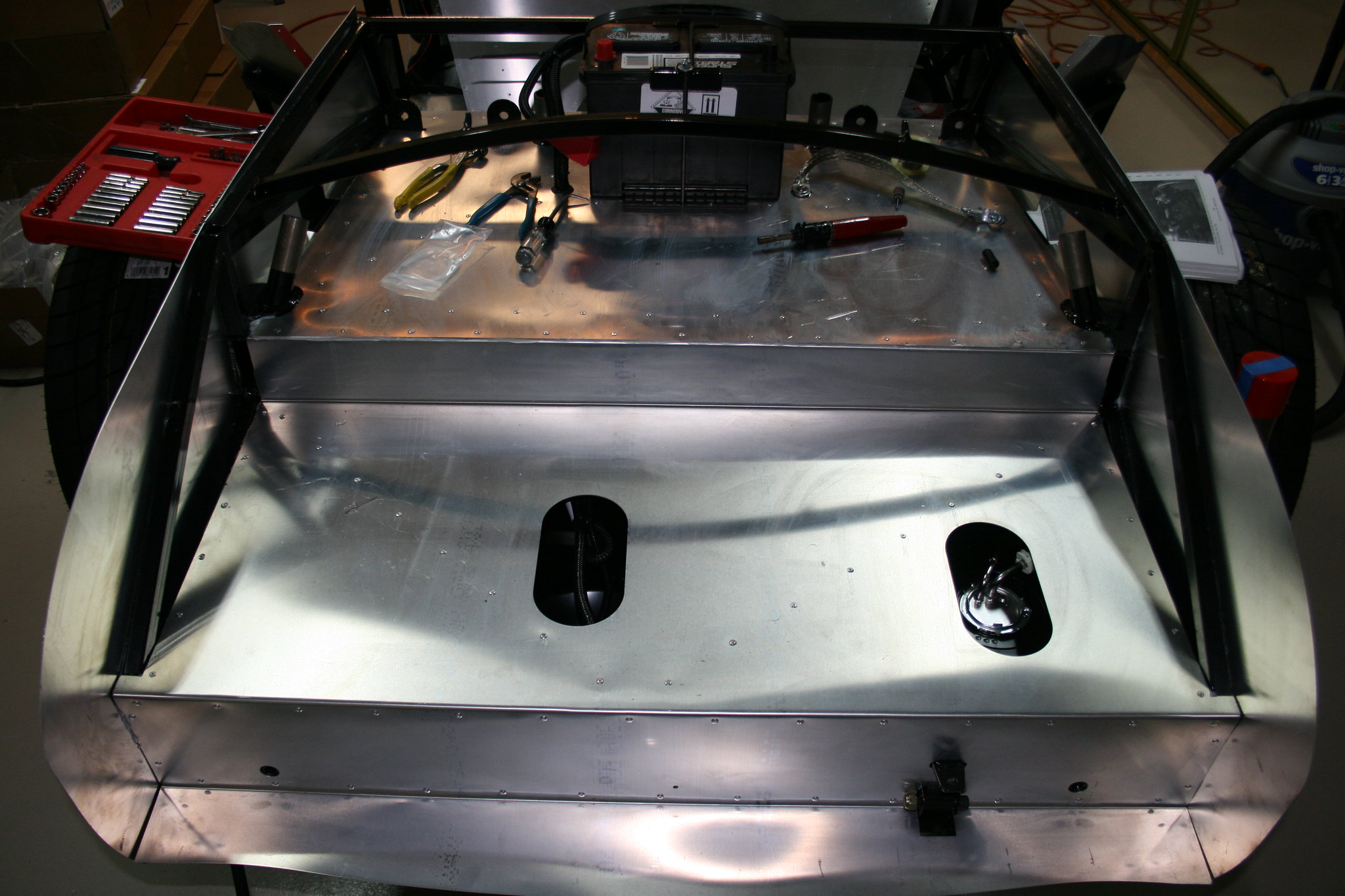
I did a little research on batteries and the one I got was one of the shortest height I could find. There's not much room in the trunk, so I need a battery that's short and stout.
I also attached the majority of the remaining truck sheet metal.
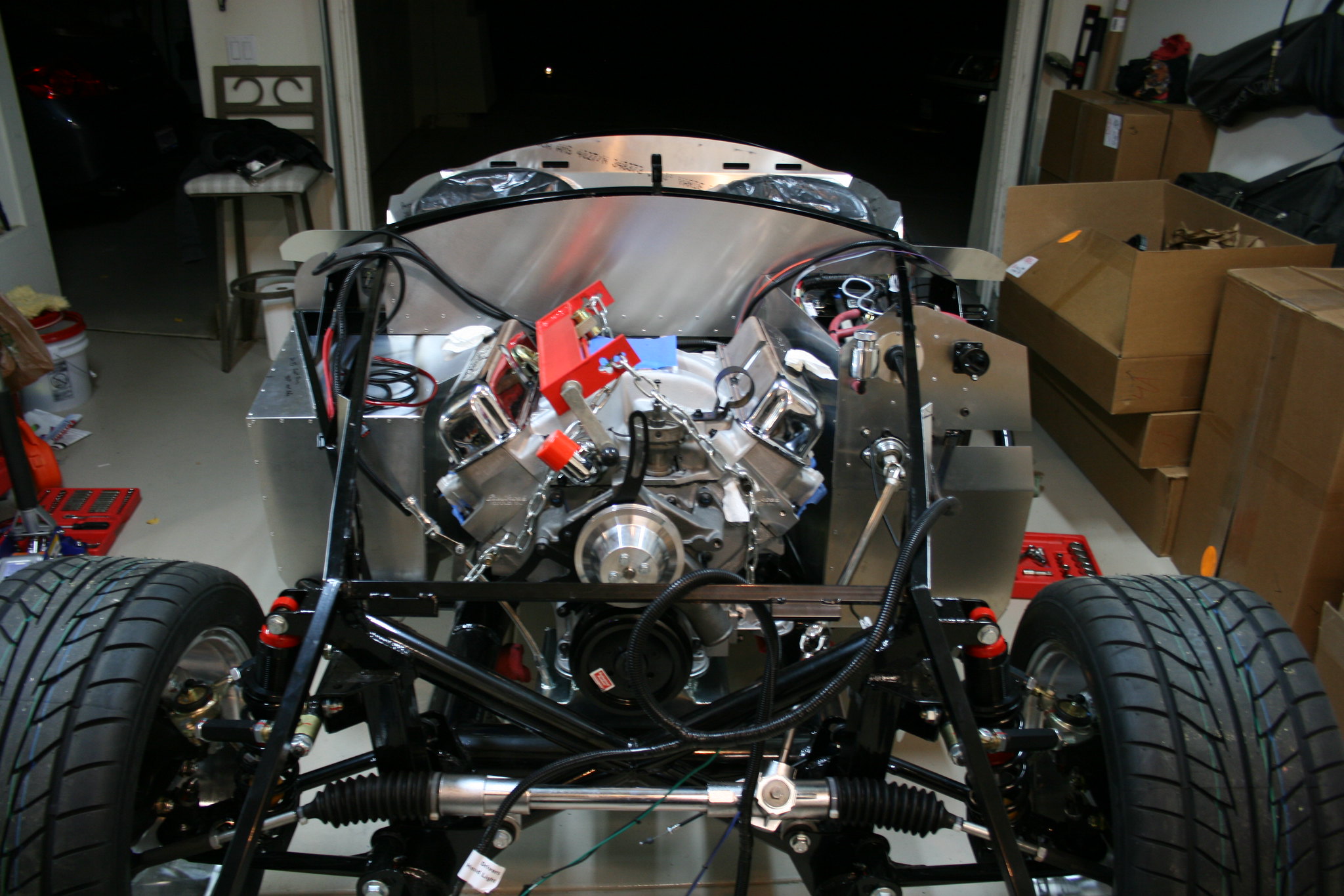
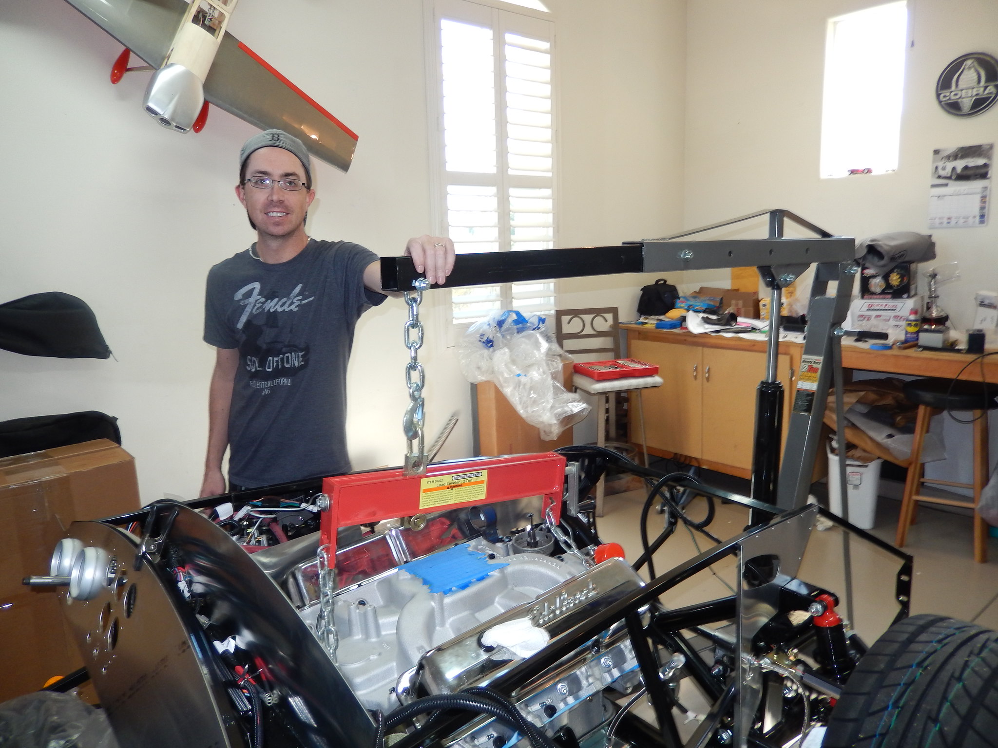
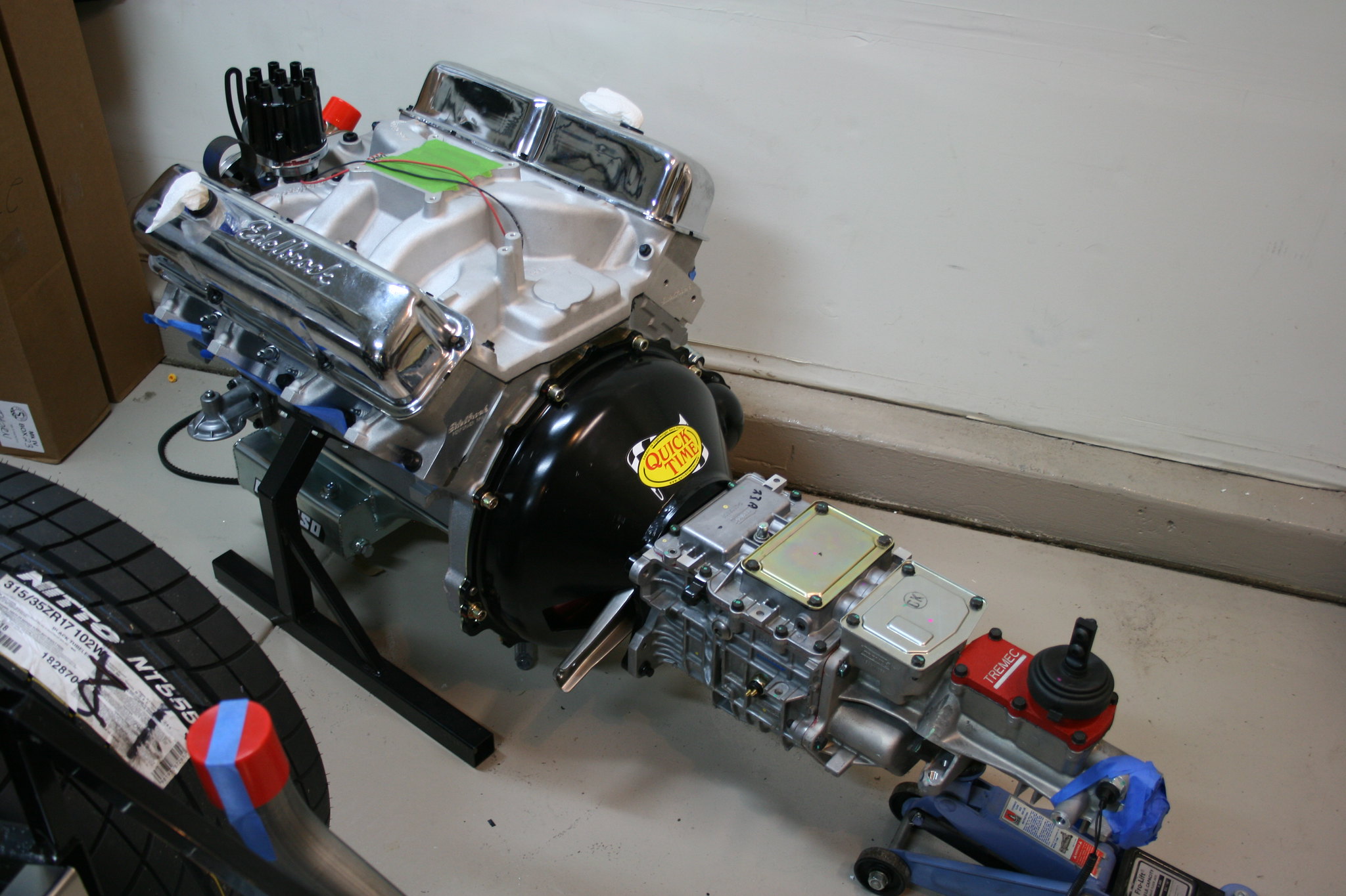
With the engine and transmission all assembled it was time to put it in the car. First I had to attach the engine mounts to the engine. Once I had them attached I had to figure out how I was going to safely attach nearly 1000lbs to the engine hoist. I ended up using 2 bolts where the bellhousing attached and 2 bolts at the front of the engine. With that figured out the rest was pretty easy actually. The load leveler let me change the angle and the hoist did all the hard work.
Next I decided to lay in some harnessing before assembling and install the engine and transmission. I loosely laid the harness on the frame attaching it temporarily with zip ties and putting the ends of the harness in the general location where they'd be finally attached.
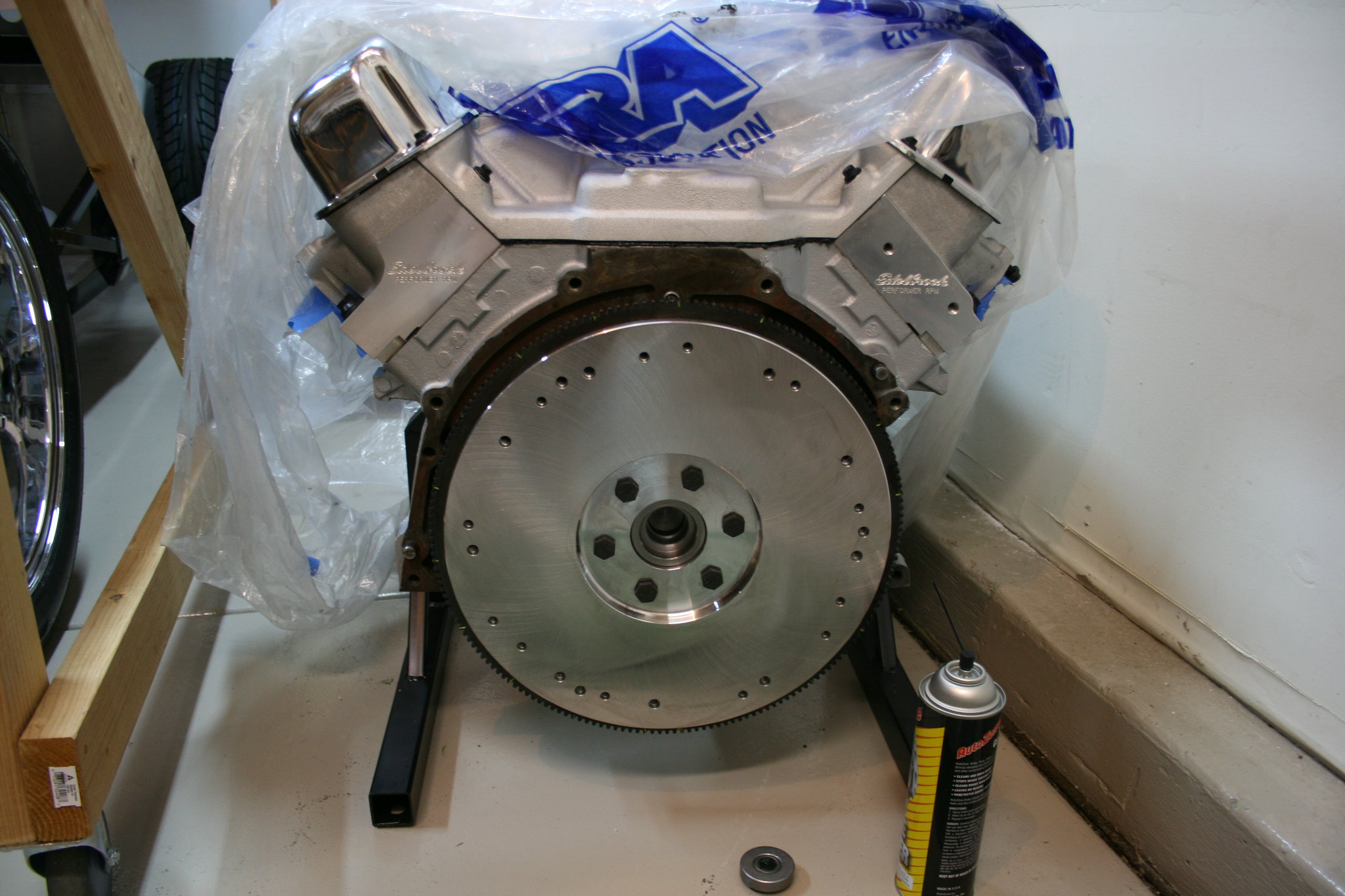
Once I was satisfied with the layout I started assembling the engine to the transmission. First, flywheel and pilot bearing agttach to crankshaft
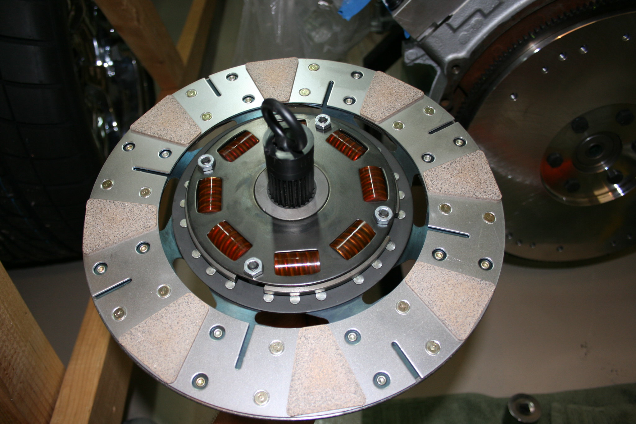
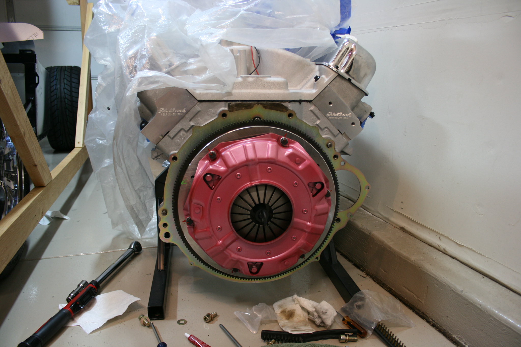
Then, clutch disc is sandwiched between pressure plate and flywheel.
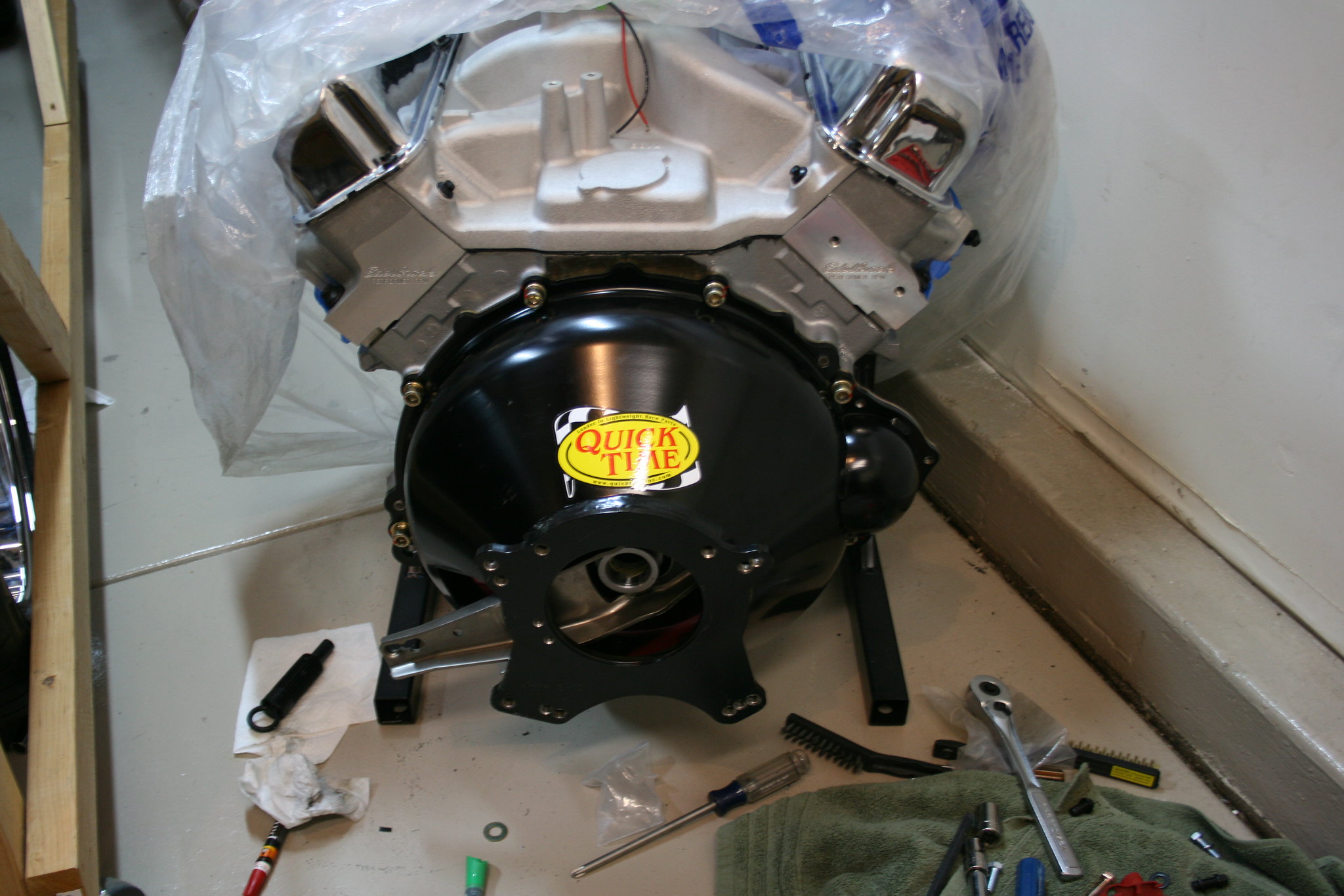
Then, the clutch fork and throwout bearing are assembled and installed into the bellhousing, and the bellhousing is attached to the engine. In this application I had to shorten the pivot bolt that the clutch fork attaches to in order to keep the throw out bearing from riding on the pressure plate.
With that all assembled next it was time to attach the transmission to the bellhousing. I ran into a little trouble at this point because the pressure plate alignment tool could not hold the pressure plate in line with the pilot bearing while I was bolting up the pressure plate, I ended up using a clamp to actuate the clutch while I installed the transmission so that it could all slide together.
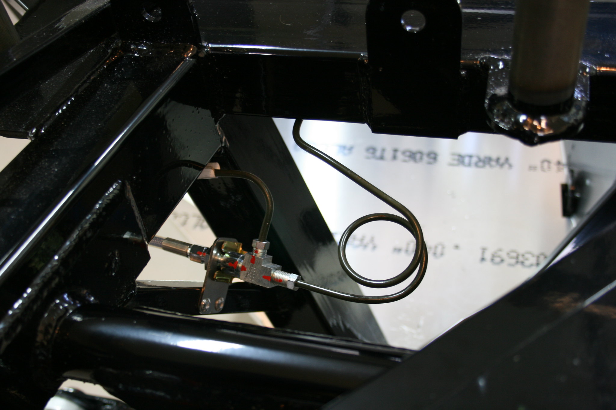
Next it was on to plumbing the brake lines. 3/16" brake line is much easier to bend than the steel fuel line was. I pretty much stuck to the book on this portion. Trying to hide the lines as best I could. Once I had all the hard line bent and connected. I filled the system and started bleeding the brakes. No major leaks anywhere, small leaks at the master cylinders went away after tightening the fittings just a bit more.
Brake pedal feels pretty solid for now, but once I take that first test drive I'll know how well I bled the brakes.
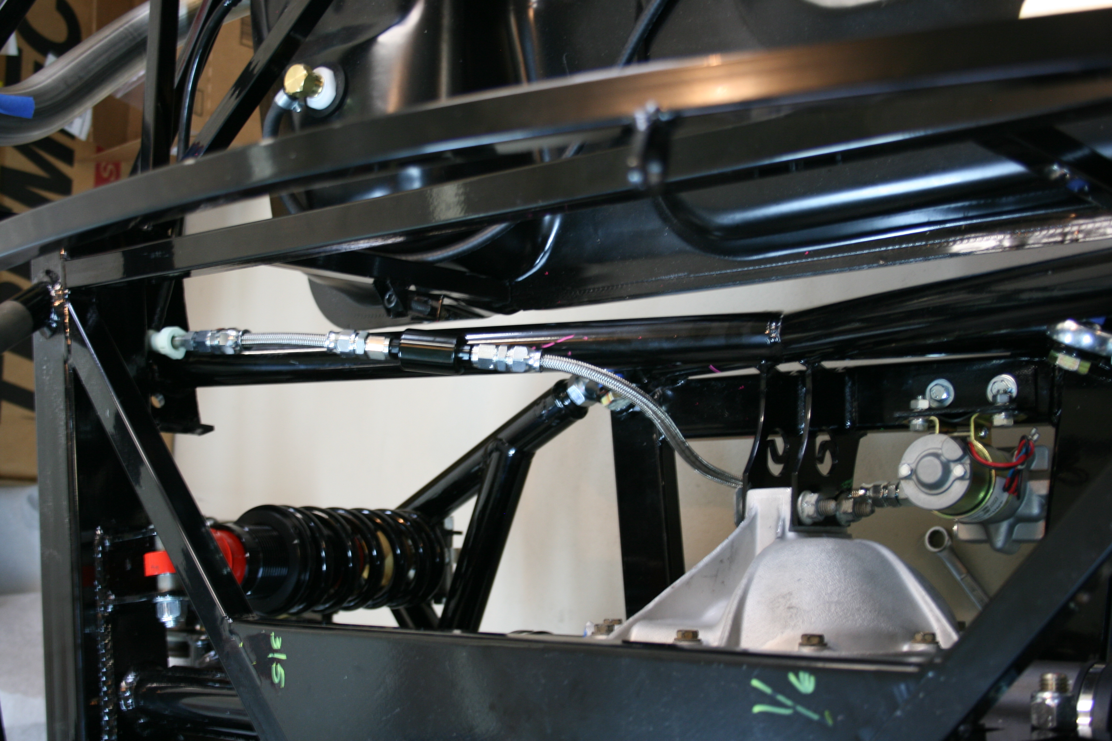
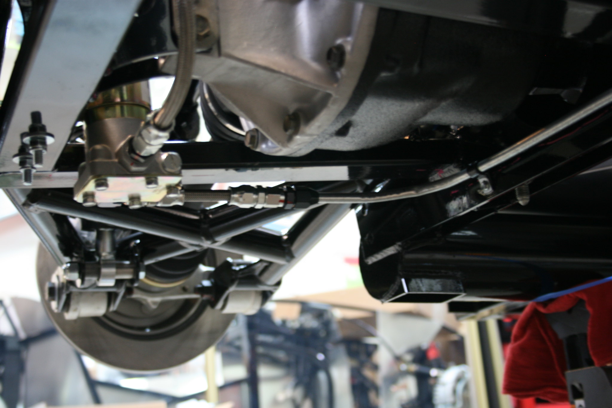
With the alignment roughly complete I moved on to the plumbing. This is one place where I deviated a bit from the plan. I ended up buying some 3/8" diameter steel hose for the fuel line instead of using the supplied 5/16". I also -6 PTFE steel braided fuel hose for all the flexible pieces. Since I wasn't using much of what was supplied, I also had to buy a whole bunch of fittings. I also decided on an external electric fuel pump (Mr. gasket P95 or 95P). There really no designated place to mount the fuel pump so I made a bracket, painted it, and bolted it to the frame near the rear end.
Anyway once I found suitable places to mount the fuel filters and fuel pump I started bending the steel tube. I went through 2 sets of cheap tubing benders from O'reilly before I decide it was just going to be easier to bend by hand. Luckily I only had to make around 4 bends to get it shaped right.
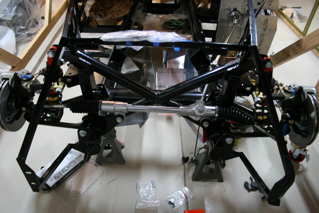
With all the suspension and steering components installed I decided to do an alignment. So I put the wheels on it and go it set to 4" ride height. I did the rear first and then the front. It was A LOT of, measure, jacking it up, making an adjustment, set it back down. I feel like I've got it pretty close now. I did realize that I don't have the steering rack centered meaning that it's about 2.5 turns to full left and about 3 turns to full right. I'll have to make more adjustments, but I'll wait until after the engine is installed.
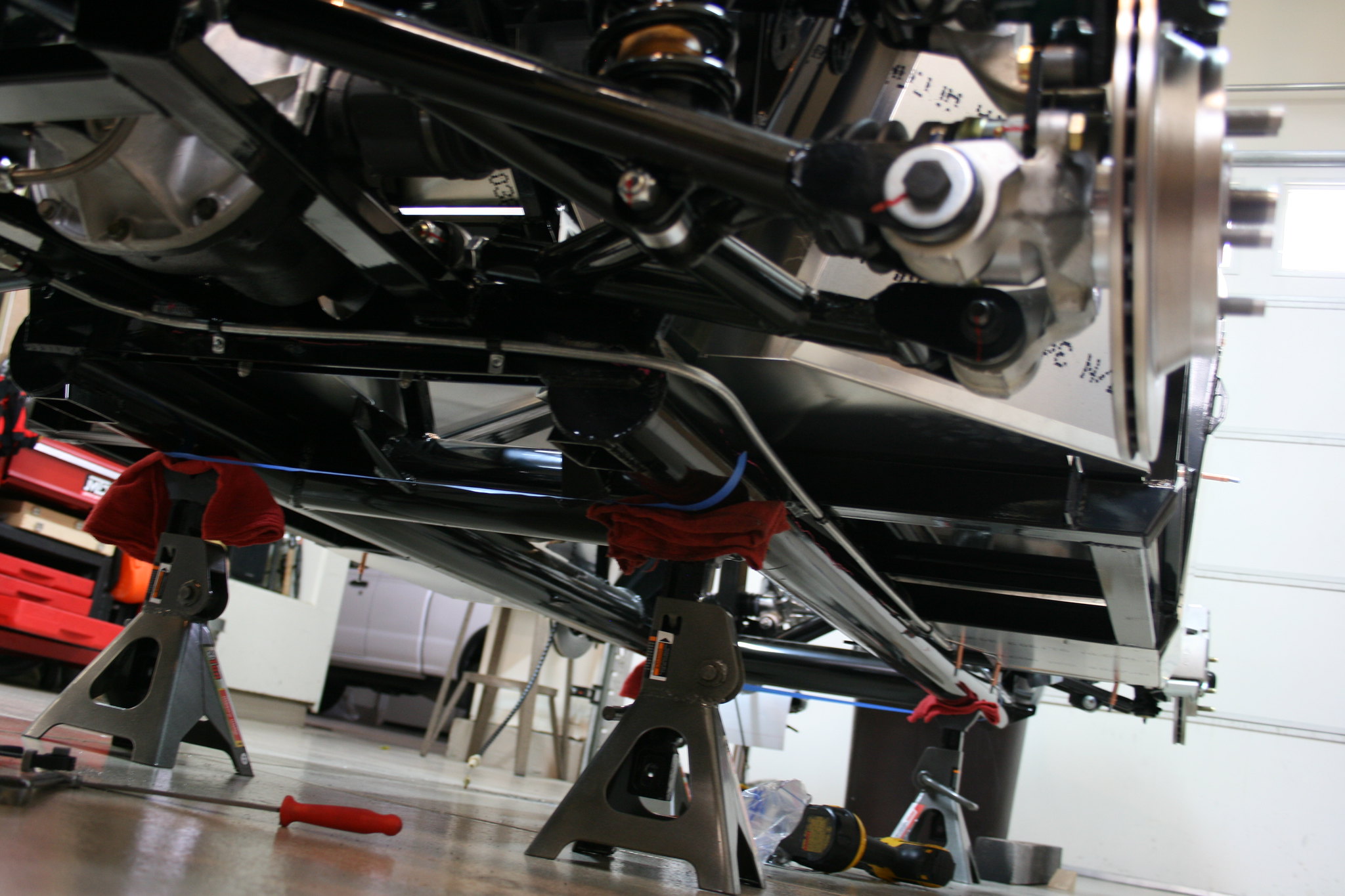
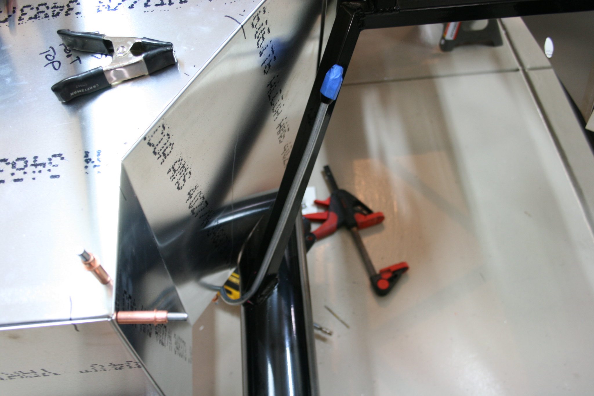
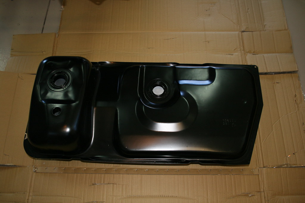
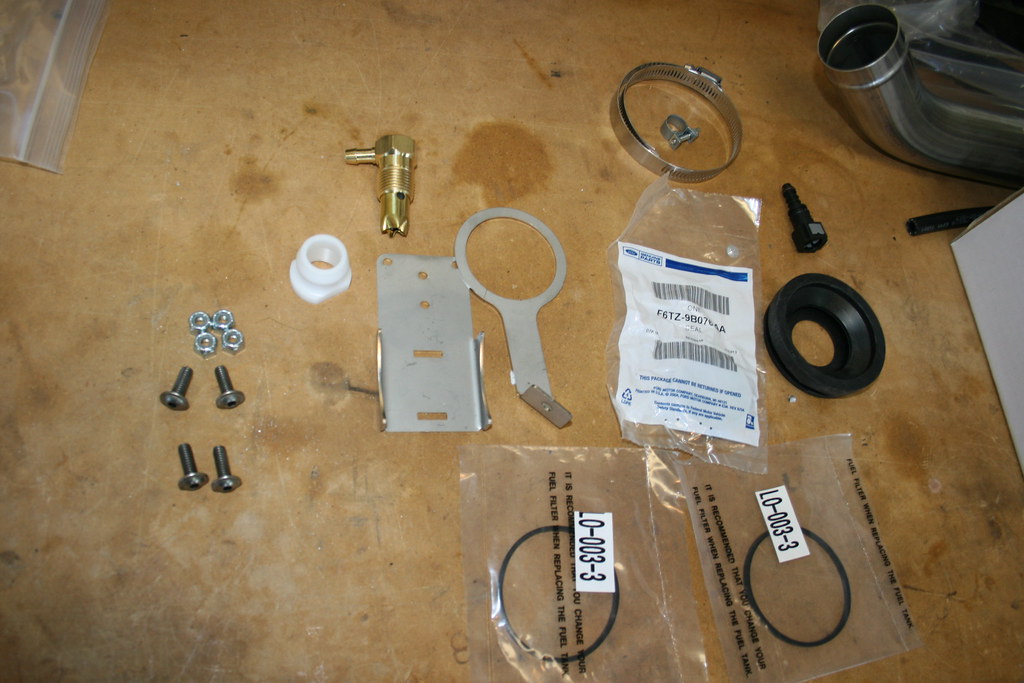
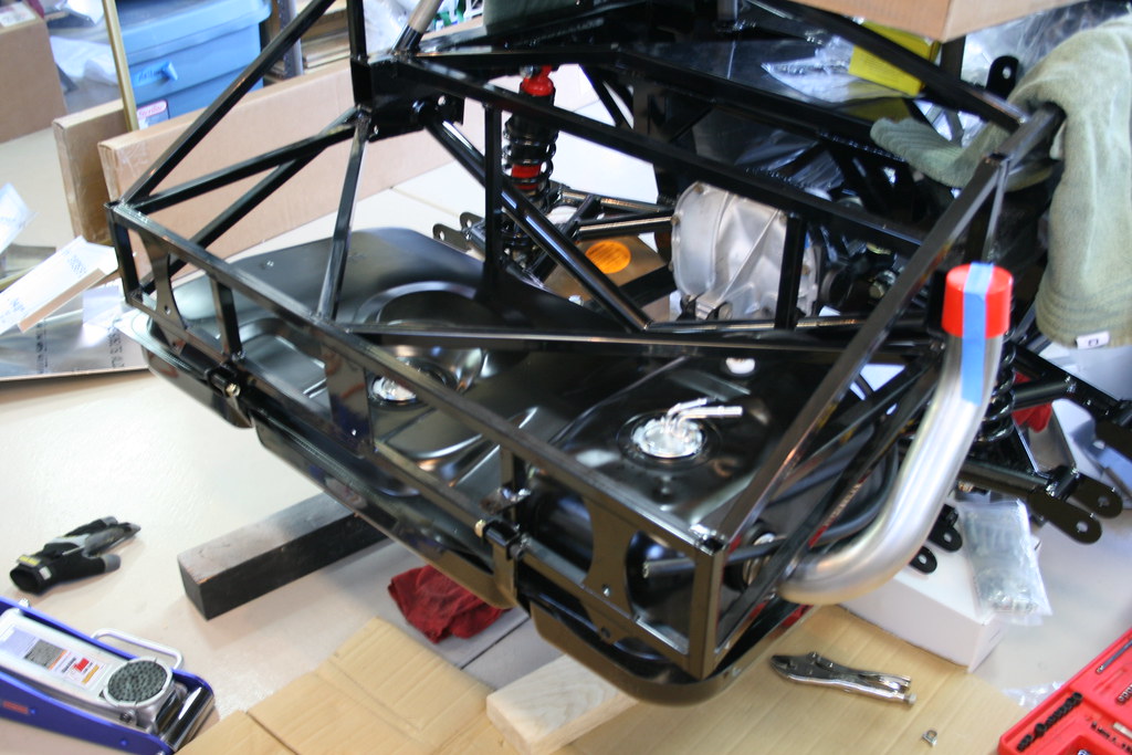
Next came assembling and installing the fuel tank.
Assembling the tank wasn't too much trouble, but getting the assembled tank mounted was a bit of a challenge.
The fuel filler tube was just hitting the frame when it was fully seated. After reading what others had done on ffcars.com forum I decided to just bend the tube slightly for clearance. I've got it clearing the frame now, but I won't truly know until the body is mounted and the filler hose is attached how much clearance there is.
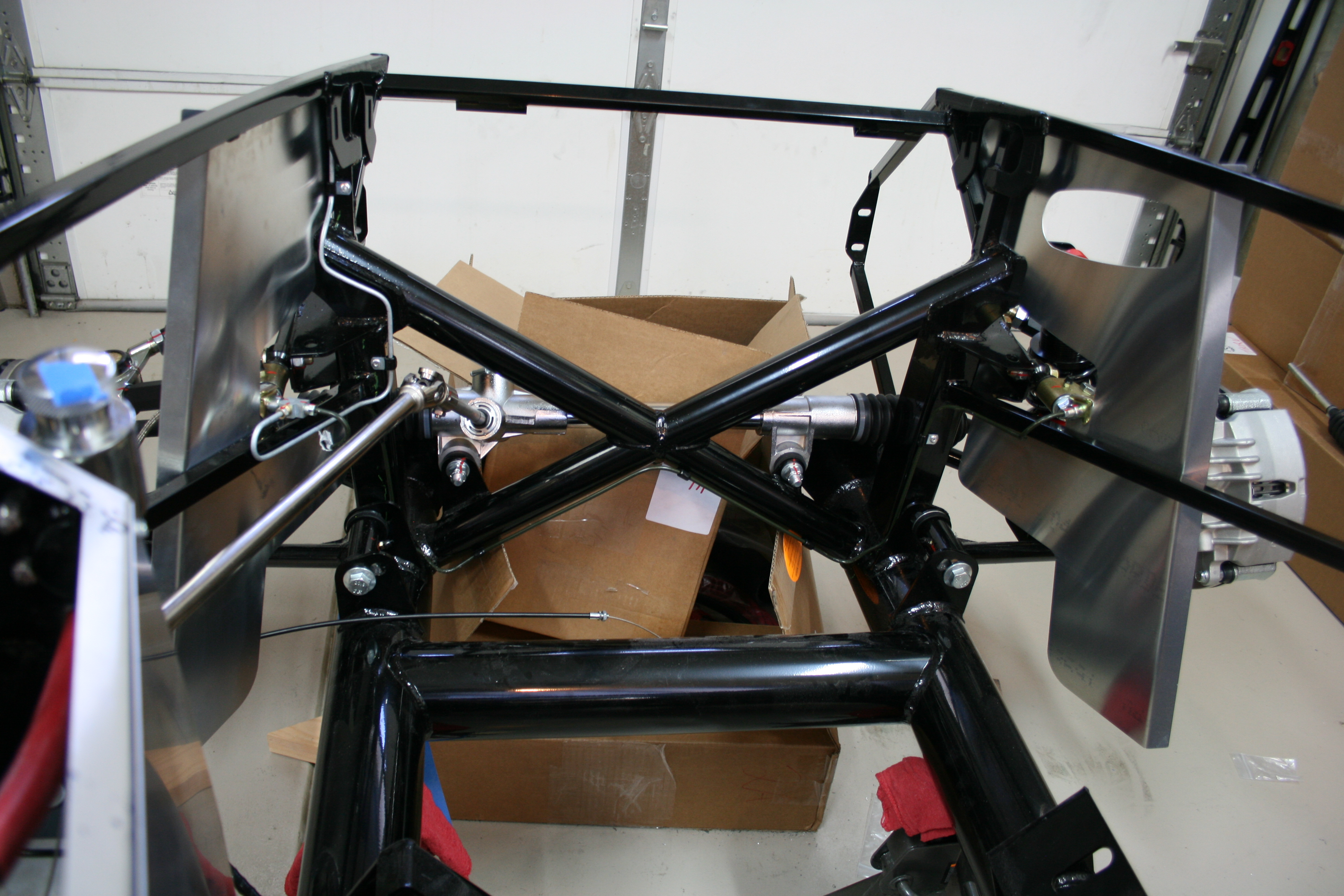
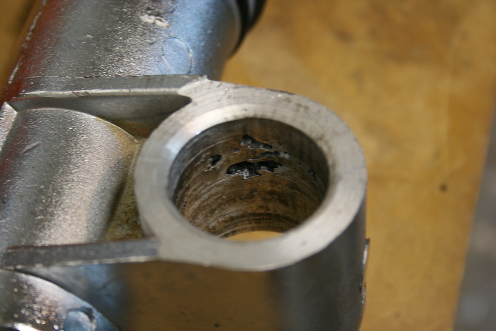
The steering rack came in with the rest of the kit, but when I went to install it I noticed a flaw in the casting where the bushings are installed.
I sent this picture to Factory Five and they said they'd ship a whole new rack out to me. Didn't have to return this one or anything. A week or two later the new one arrived and I was able to get it installed.
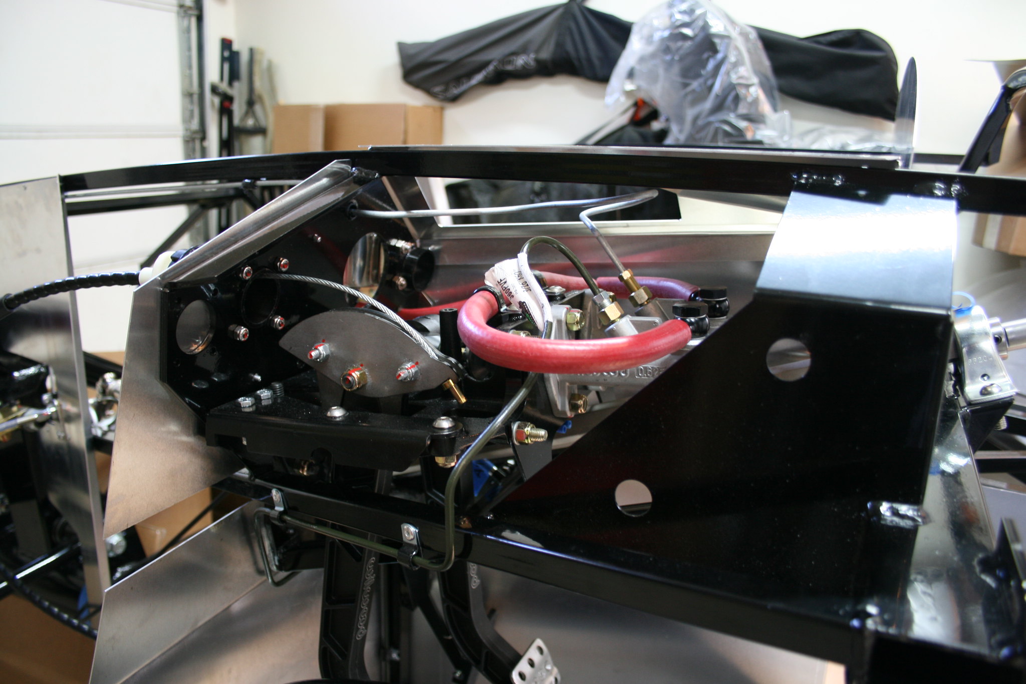
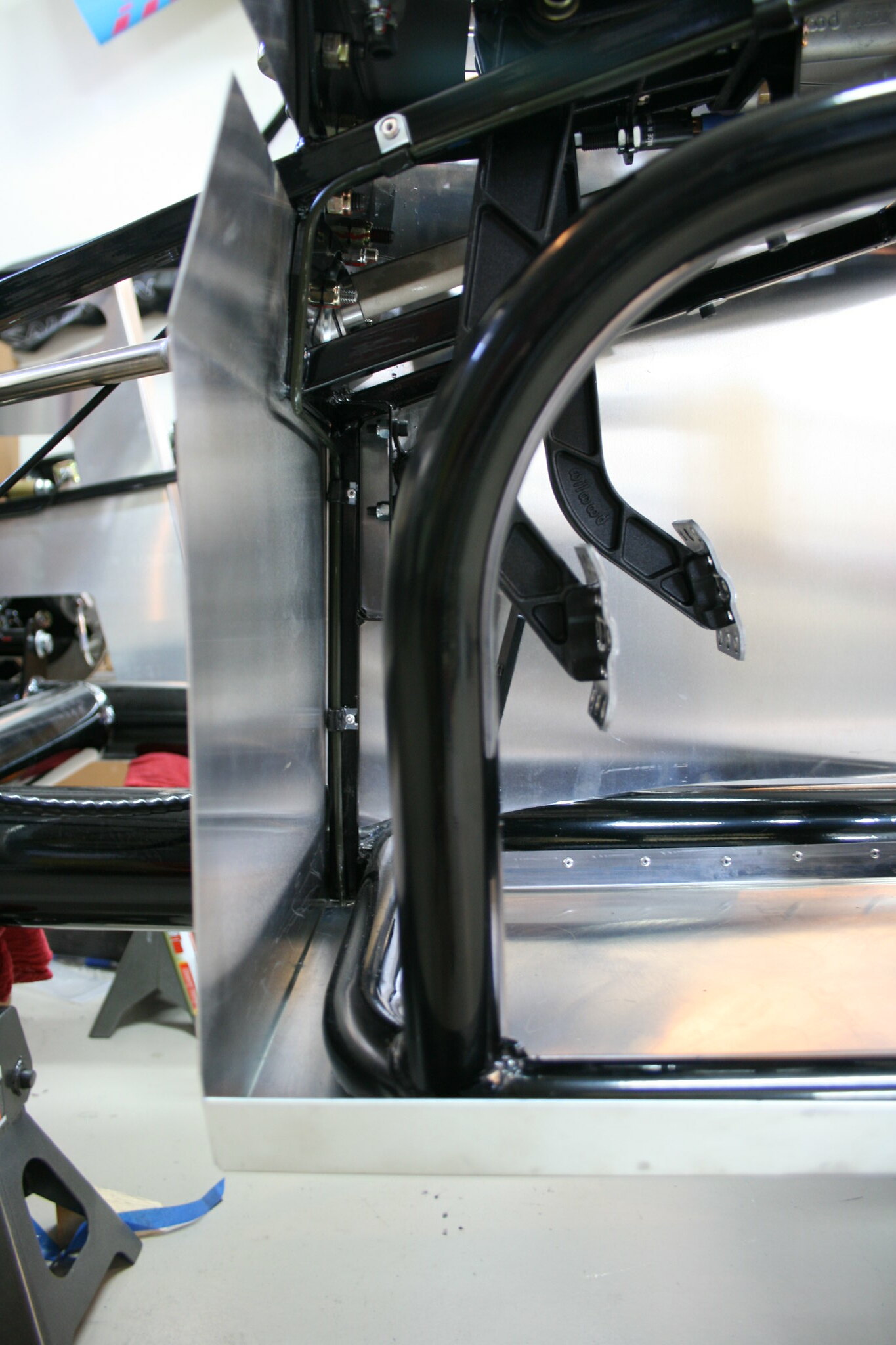
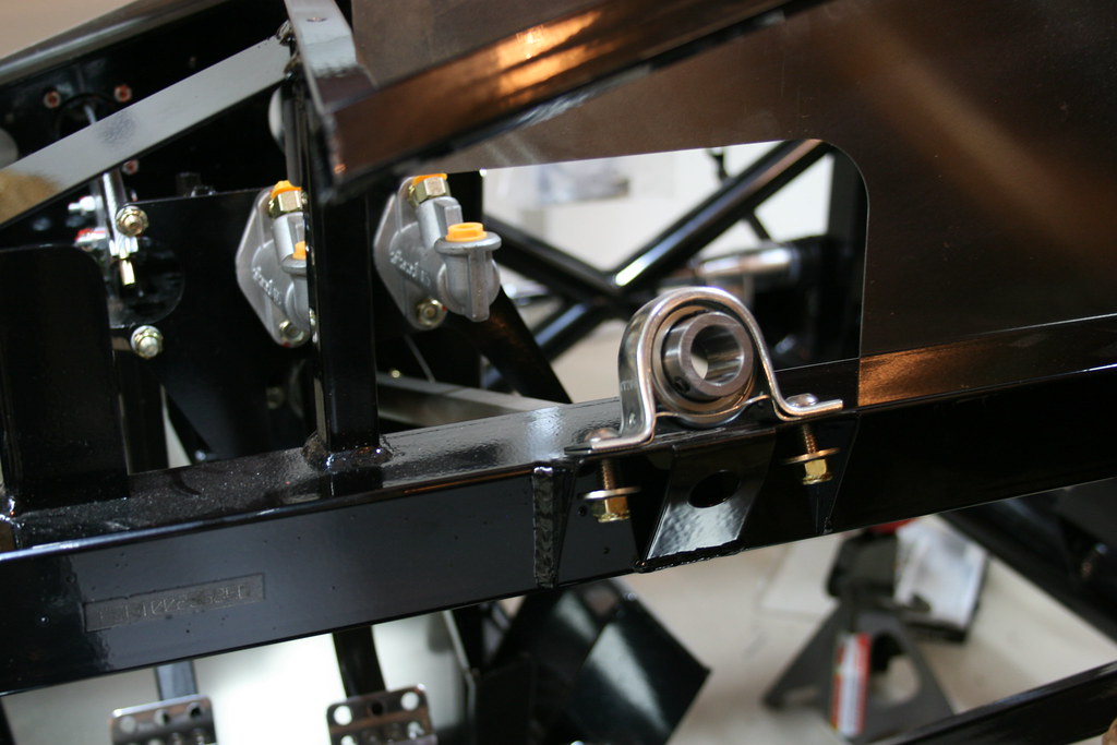
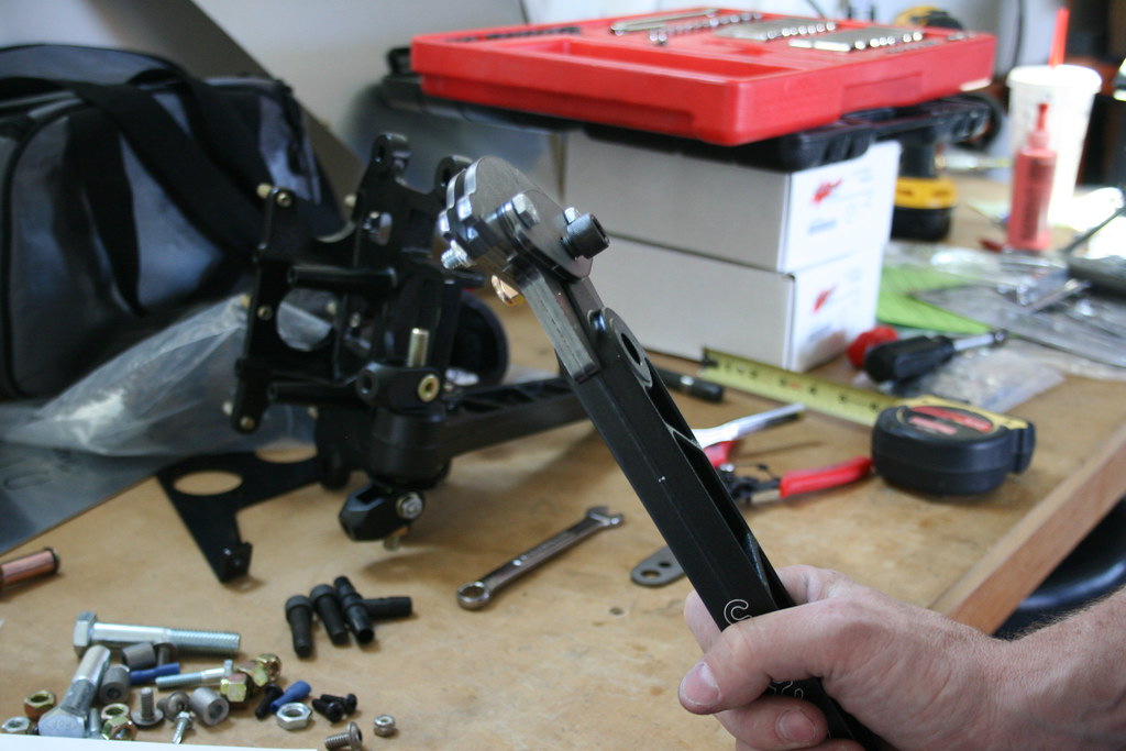
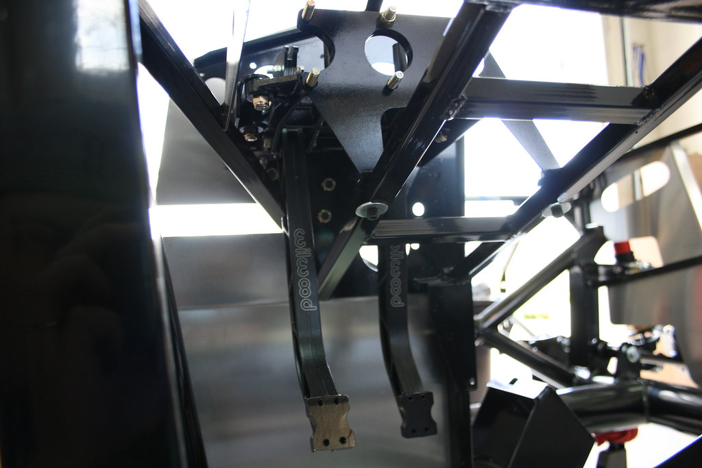
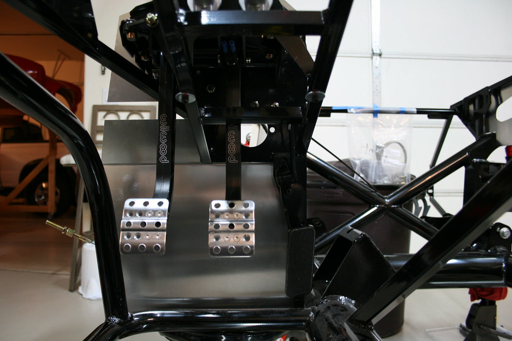
Next came the pedal assembly. It's a Wilwood kit that factory five includes with the rest of kit. Nothing too tricky with this pedal assembly kit. The only issue I ran into was the clutch pedal hitting part of the frame when it was fully depressed. I notched the pedal arm for clearance. Really it probably wasn't necessary, but now I definitely don't have to worry about the pedal crashing into the frame.
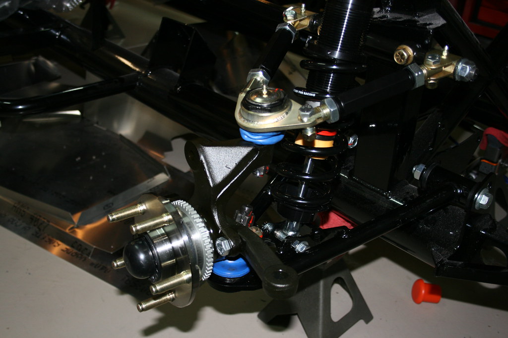
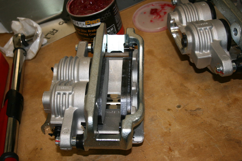
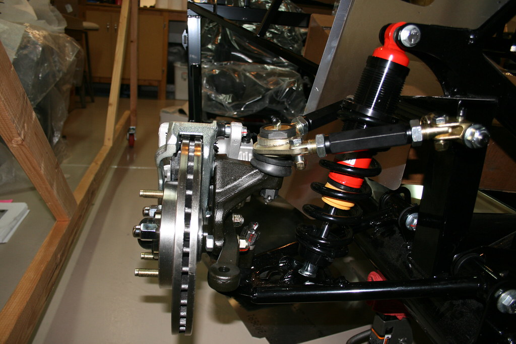
By now the brakes and spindles had arrived so I was able to finish up the front assembly. I had one torn dust boot (the blue things) so I decided to replace them all with some new ones from Energy Suspension.
I also realized that I had initially installed the steering arms on the wrong sides. The hole should be smaller on the top than on the bottom. Itorder to remove thos you have to remove the spindle from the lower control arm. In order to get a socket on the lower ball joint nut you have to remove the upper ball joint from the spindle. So I basically assembled the spindles to the control arms twice :).